Getting Started with Free/Lite Edition
Administration Videos
AWS Quickstart: Encrypted Overlay Network
VNS3 in AWS
Routing to and from plugins
Azure VPN to VNS3 via IPSec
VNS3 in Azure
Configuring VNS3 via the API
Multi-Cloud with Terraform and VNS3
Multi-Region Peering mesh with Terraform and VNS3
Creating IPsets with VNS3 API
Route-based VPN with the API
VNS3 Troubleshooting Videos
Google Cloud Platform VPNGetting Started with Free/Lite Edition
Table of Contents
Introduction
VNS3 is an Appliance as a Service that provides network security and connectivity: A Security Appliance, Application Delivery Controller and Unified Threat Management all rolled into one - to your cloud-based applications.

Requirements
- You have a cloud account that Cohesive can use for enabling your access to the VNS3 Controller AMIs (via Cloud Provider Marketplace or private Image permissions).
- Ability to configure a client (whether desktop based or cloud based) to use OpenVPN client software.
You have a compliant IPsec firewall/router networking device:
Preferred: Most models from Cisco Systems*, Juniper, Watchguard, Dell SONICWALL, Netgear, Fortinet, Barracuda Networks, Check Point*, Zyxel USA, McAfee Retail, Citrix Systems, Hewlett Packard, D-Link, WatchGuard, Palo Alto Networks, OpenSwan, pfSense, and Vyatta.
Best Effort: Any IPsec device that supports: IKE1 or IKE2, AES256 or AES128 or 3DES, SHA1 or MD5, and most importantly NAT-Traversal standards.
Known Exclusions: Checkpoint R65-R80 require native IPSec connections as Checkpoint does not conform to NAT-Traversal Standards in these versions. In Checkpoint R80+, GuiDBedit must be used to force either native IPsec or NAT-T in order to maintain a reliable connection. (See https://support.cohesive.net/support/solutions/articles/31000156433-nat-t-compatibility-with-check-point-devices)
Cisco ASA 8.4(2)-8.4(any) bugs prevent a stable connection from being maintained.
Firewall Setup
VNS3 Controller instances use the following TCP and UDP ports, they are allowed by default in the controller’s internal firewall, and cloud security groups should be set accordingly:
- UDP port 1194 - (OpenVPN-based overlay networks) For client VPN connections; must be accessible from all servers that will join VNS3 topology as clients.
- UDP port 51820 - (Wireguard-based overlay networks) For client VPN connections; must be accessible from all devices that will join VNS3 topology as clients.
- UDP 1195-1203 (OpenVPN-based peering network in versions 5.x or earlier) - For tunnels between Controller peers; must be accessible from all peers in a given topology. VNS3 Free and VNS3 Lite Edition will not require UDP ports 1195-1197 access as they are not licensed for Controller Peering.
- UDP 1201-1208 (Wireguard-based peering network in versions 6.x or later) - For encrypted peering tunnels between Controller peers; must be accessible from all peers in a given topology. VNS3 Free and VNS3 Lite Edition will not require UDP ports 1201 -1208 access as they are not licensed for Controller Peering.
- TCP port 8000 - HTTPS admin interface and API; must be accessible from hosts where you will want to obtain runtime status or configure peering, also needs to be open to and from the Controllers at least for the peering process, and needs to be accessible when downloading credentials for installation on overlay network clients.
- UDP port 500 - UDP port 500 is used for the phase 1 or IKE (Internet Key Exchange) component of an IPsec VPN connection.
- Protocol 50 - This is used for the phase 2 or ESP (Encapsulated Security Payload) component of an IPsec VPN connection only when negotiating with native IPsec.
- UDP port 4500 - This is used for the phase 2 or ESP (Encapsulated Security Payload) component of an IPsec VPN connection when using NAT-Traversal Encapsulation.
- TCP ports 80 and 443 - The internal firewall of VNS3 initially allows these ports to help customers who don’t realize the VNS3 UI and API runs on port 8000, to receive a redirect. PLEASE DISABLE THESE PORTS, ideally in BOTH the VNS3 firewall (INPUT -p tcp –dports 80,443 -j DROP) and in the cloud security groups.
Addressing Considerations
VNS3 requires an Overlay Network subnet to be specified as part of the configuration process. Use of the Overlay Network is optional but provides improvements in security, address mobility, and performance.
Your VPC CIDR and Subnets cannot not overlap with the VNS3 Overlay Network Subnet to prevent routing issues.
AWS VPC allows virtual machine instances to act as networks gateways for unencrypted VPC traffic. Routing traffic from the unencrypted VPC instead of using the encrypted Overlay Network requires configuring the AWS Routing Tables and disabling the Source/Destination Check on the VNS3 instance. See the unencrypted VPC section at the end of the document for more details on configuration.
Getting Help
At Cohesive Networks we pride ourselves on the quality support we provide to our users and customers. We want to make sure you have all the materials to be independently successful with VNS3. In cases where you do need help, don’t hesitate to reach out to one of our support specialists.
Support Contacts
- Create a support ticket.
- 24x7 Response - Call the number provided in your contract or contact us.
- Services and Solutions Support - Contact us
Support Detail
- Support Site - Our support site provides FAQ and known issue information.
- Support Plans - Check out our support plans for access to our support team
- Support FAQ - Common questions and answers
- Want 27x7 support? [Contact our sales team!](<mailto:sales@cohesive.net)
Remote Support
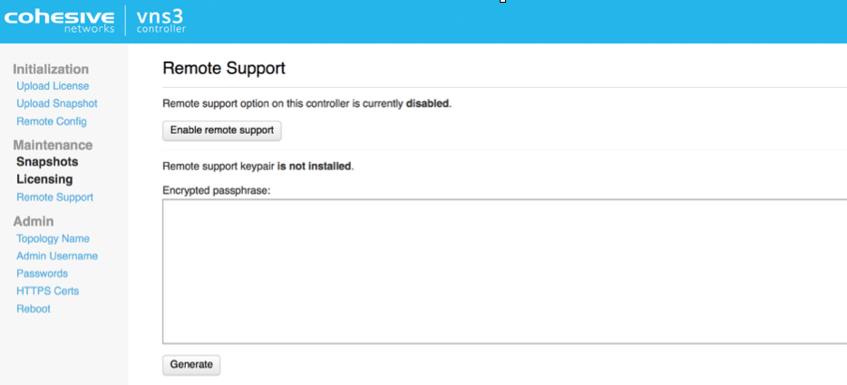
In the event Cohesive needs to observe runtime state of a VNS3 Controller in response to a tech support request, we will ask you to open Security Group access to TCP port 22 (SSH) from our support IP, 54.236.197.84, and Enable Remote Support via the Web UI.
Note that TCP 22 (ssh) is not required for normal operations.
Each VNS3 Controller is running a restricted SSH daemon, with access limited only to Cohesive for debugging purposes controlled by the user via the Remote Support toggle and key exchange generation.
Cohesive will send you an encrypted passphrase to generate a private key used by Cohesive Support staff to access your Controller. Access to the restricted SSH daemon is completely controlled by the user. Once the support ticket has been closed you can disable remote support access and invalidate the access key.

Login and Configuration
Login to the VNS3 Web UI - https://your-controller-ip:8000
Default username: vnscubed.
AWS - default password is the instance id (i-xxxxxxxx).
Google - default password is the instance id
Azure - Default password is derived from instance name and private ip:
<azure instance name>-<azure private ip>. For example, if the Azure instance name is “my-vns3” and the private VNET IP is “10.0.0.9”, the password is “my-vns3-10.0.0.9”. (This is because the Azure portal does not make the virtual instance ID readily visible.)In legacy versions prior to 4.4.0, the default password in Azure is “vnscubed”.
Reset your passwords: Reset the Web UI Password - Even though the instance id is unlikely to be “guessed”, please change it for security purposes. Reset the API Password. Making it a different password than the web interface is probably best.
![VNS3 Reset PS UI] (https://cohesive-networks.s3.amazonaws.com/docs/images/vns3-config-login.png#medium “VNS3 RESET PS”)
NOTE: Your VNS3 Controller answers to API calls on the same port 8000 as the web interface runs on. Ideally make a separate password for the API usage against the Controller.
Cohesive does not have any key access or remote access to your VNS3 Controllers unless provided by you. If you forget these passwords we cannot recover them for you.
Pre-Configured Overlay Network
VNS3 version 4.3.3 and higher Free and Lite Edition images launched through the cloud marketplace are completely initialized with unique Overlay client credentials generated on first boot. This allows for simpler and faster deployment.
The Overlay Network functionality is optional but the Overlay Network needs to be set in order for the VNS3 controller to function.
In order to provide this preconfigured functionality, Cohesive Networks has selected a small Overlay Network CIDR in the Carrier Grade NAT reserved address space of 100.64.0.0/10 (RFC 6598). This preconfigured Overlay Network ensures no overlap with the underlying cloud network configuration or remote networks that will connect via VNS3 VPN functionality.
Preconfigured Overlay Network for Free and Lite Editions - 100.127.255.192 / 26.

In situations where a different Overlay Network is desired follow the steps to reset and re-initialize the controller following steps outlined on page 15 of this guide.
About the Overlay
The VNS3 Overlay Network is an optional feature that provides end-to-end encryption, increased performance (in most cloud environments), and ip address mobility across regions and cloud providers.
The Overlay Network is an essential component to the shared responsibility/trust model when running workloads in a 3rd party controlled environment like public cloud. Our customers use the Overlay Network to meet and exceed industry regulations like HIPAA, PCI, and NIST Cybersecurity Framework or internal IT requirement when migrating to cloud.
To deploy the Overlay Network, unique cryptographic X.509 keys (generated on the VNS3 controller) and tied to a specific IP address in the Overlay Network subnet are distributed to the cloud or remote servers. These IP credentials are then used with a TLS client (like OpenVPN) to make an encrypted connection back to the VNS3 controller or VNS3 controller mesh. All communication between devices in the Overlay is passed through the VNS3 encrypted switch and depending on the use-case, communication to remote networks or the public Internet can routed through VNS3 as well.
Controller Status
Once the passwords have been set, click status to view the Runtime Status page for a summary of all runtime configuration information.

- Controller Status - The Controller’s identity within the Overlay Network (which was setup in the Peering steps) is displayed in this section.
- Peers and Clients - Connections to other Controllers (called Peers) and client servers (called clients) are displayed in this section. If you setup a multiple Controller topology in the Peering steps you will see a Peered Controller listed. If you setup a single Controller topology, you will see no Peers.
- System Status - Instance level information is displayed in this section.
The VNS3 Controller is ready for connections to be added. We recommend starting with configuring any IPsec connections that are needed before connecting client servers via clientpacks.
Next Steps
Optional - Reset Defaults
As previously mentioned VNS3 Free and Lite Editions come preconfigured with a 100.127.255.192/26 Overlay Network.
There are some situations where you will need to use a different Overlay Networks address space for your specific use-case. Reasons could include but are not limited to, using a specific CIDR that fits with your organizational internal/external addressing requirements or increasing the size of the Overlay Network for growth future proofing.
This OPTIONAL section outlines the steps required when the preconfigured Overlay Network subnet needs to be changed.
Reset Overlay
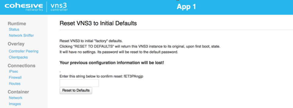
Reset Factory Defaults removes all configurations, licensing and settings on a particular VNS3 Controller instance. The only configuration parameter that will remain is the username and password (both UI and API) set on the Controller instance at the time of the reset operation.
To Reset Factory Defaults navigate to https://
On the resulting page enter the code displayed to validate the reset and click Reset.

After Reboot, the Controller is reset and you can choose how to configure starting with Initialization.
Configure Overlay Network Address
WARNING: YOUR OVERLAY NETWORK RANGE CANNOT OVERLAP WITH THE CLOUD SUBNET/VPC/VNET.
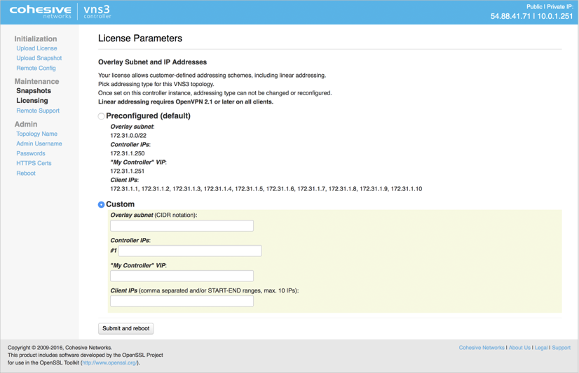
The resulting screen allows you to choose the VNS3 Overlay Network to be used by your cloud-based client servers. Click the Custom Radio button to specify a custom subnet range.
The required fields are:
- Overlay Subnet CIDR (defines the range of addresses that will be available to your Overlay Subnet)
- Controller IPs (each Controller is a member of the Overlay Subnet on the specific addresses defined)
- “My Controller” VIP (an Overlay IP address used by the Controllers for peering and syncing)
- Client IPs (the actual IPs that will be available for your cloud-based Overlay Subnet client servers).
Once you complete this step, the Controller instance will reboot itself and will come up with your specified topology enabled and running.

Click Submit and reboot.
Generate Keys on VNS3 Controller
The Controller is now configured to the License specs (how many Controllers it can peer with, how many clientpacks are available, and how many ipsec links are available).
The first step in Controller configuration is to generate the X.509 cryptographic keys associated with each Overlay Network IP called clientpacks. The clientpacks are used along with an SSL client (OpenVPN is recommended) to connect a client server to the Overlay Network using a specific IP address over an encrypted SSL tunnel. Click Generate New under Overlay in the left column.
During key generation you can specify a Topology name to be displayed in the Controller UI for a given set of peered Controllers. This can be changed at anytime by clicking on the Topology Name under Admin in the left column menu.
Also specify a security token. This can be anything but record this for future use as Controller peering and configuration fetching will require you to enter this again.

Click Generate keys link. Key generator will be started in the background, and you can refresh screen to observe progress.
Peering Controllers
Controllers connect to each other in a process called Peering. Peered Controllers create a redundant, highly available and secure overlay network and share traffic load from the overlay network connected servers.

NOTE: Firewall rules added to a specific controller are not automatically synced to other controllers in the peered mesh. Click Controller Peering under Overlay.
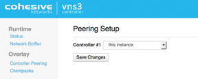
The Peering Setup Page will display the number of Controllers allowed to peer together in your topology as defined by the license file used to configure the Controller.
For Controller #1 select “this instance” from drop down, instead of specifying its IP. To be valid, your form must have “this instance” value in one and only one drop-down.
If your topology has unused Controllers, leave the extra fields set to “not set”.
If you have a multiple Controller topology, enter the Public DNS address of the second Controller for Controller #2. Repeat this for each additional Controller in your topology.
When done select Save Changes.
Updated on 16 Aug 2019
